LED Game Hoodie
The Project
At Confuzzled 2017, the theme for next year's convention was announced: "Let's Play". Essentially, gaming themed!
I wanted to make something exciting for that convention, especially since I love videogames, so I gradually came up with an idea: What if I had a hoodie that had an LED display on it? What if people were able to use a controller that let them play on this display? Effectively, I'd be creating a wearable console.
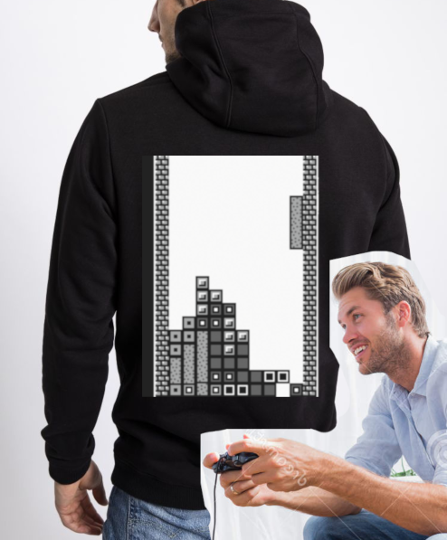
That sounded so cool, so I batted ideas around in my head for it.
The clothing part was kinda straighforward. I'd go for a hoodie design. I'd used McCall's M5252 Sewing Patterin before, creating a hoodie for Tapewolf. I was planning to give it a theme of a 90s console, so black as the primary colour with red accents. It would also be cat themed to ride the coolness vibe. Of course, there was a 90s console with that colour scheme called the Atari Jaguar, so I guessed I was following in that spirit.
There was a major question though. Should the display be on the front or the back? On the back was cool since the person could casually be doing something while someone played the game on their back, wheras on the front they would be facing the player. I had this idea that the wearer of the hoodie would also have oversized paws, and that the controller for the game would be built into the paws. This meant that in order to play, you'd have to hold the wearer by the hands, sorta. Holding their hands/paws, while looking straight at them (or at least their chest), feels a kinda intimate experience, and the idea was that you'd do this with random con-goers? Hmmmm, just seemed a little too close contact, and some friends seemed to agree. Also I was worried that the wearer having to put their arms out might interfere with the display, either by creasing the hoodie or obstructing the view of the display, though I never tested this out.
So I decided to go with the "display on the back" approach. The gamepad would take the form of the tail, which was cool since when it wasn't in use it would just hang like a regular tail, continuing the cat theme.
So.....
How do I do this?
The Pixels
I'd already discovered the how to get LEDs sewn into clothing during my Light Up Glove creation. Basically, buy a bunch of LED sequins and sew them in with conductive thread.
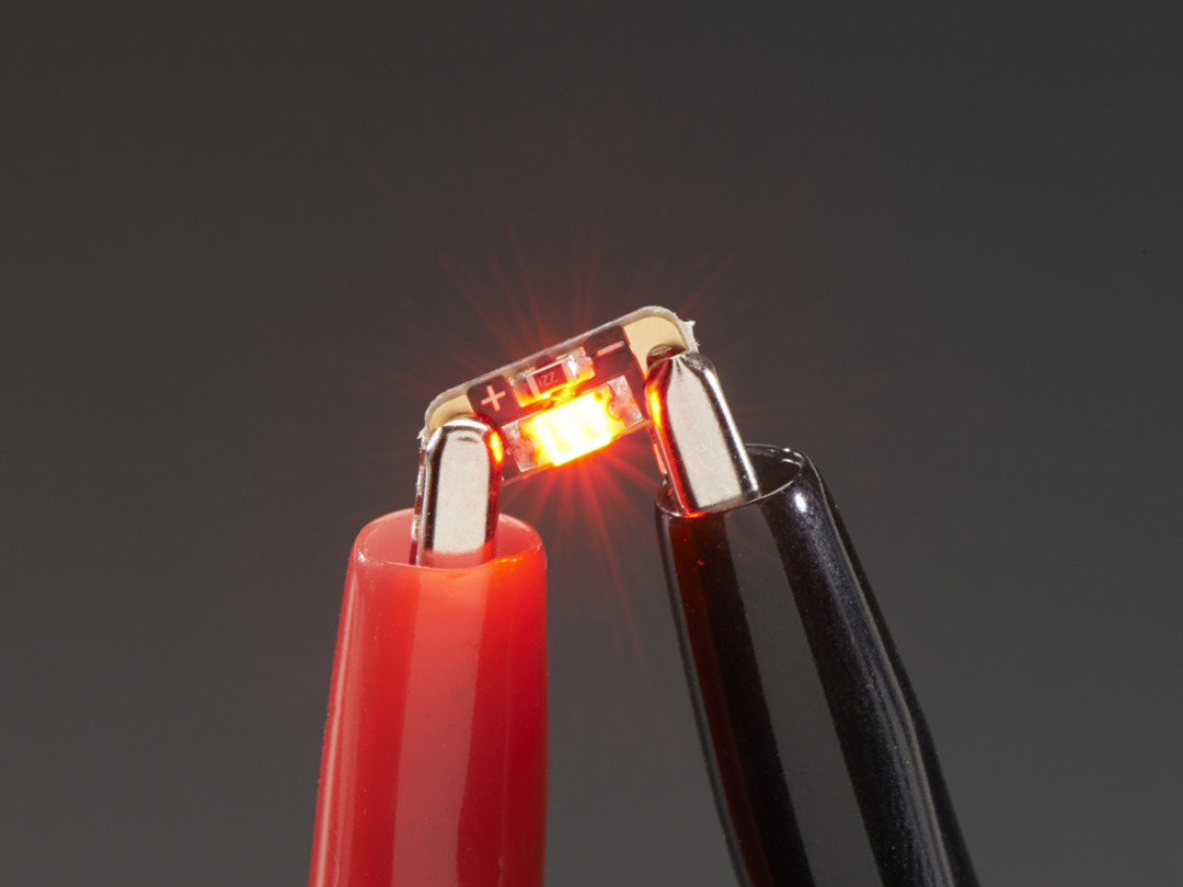
But what resolution (ie. How many pixels) should the display be?
Well, I wanted it to play Tetris, so to cover the 10 columns, I'd need it to be a minimum of 10 pixels wide. The original Game Boy version of Tetris had 18 rows, but most modern versions have closer to 20. So that's 10 columns, 20 rows
10 x 20 = 200
200 pixels.
If I wanted to do this, I would have to sew in 200 LED sequins into the back of the hoodie.
Whoa.
I looked for an alternative approach, but a mix of giving up and sheer stubborness made me insist it had to be done this way. Sure, I love to optimise stuff, but I just felt I had to sew on those 200 sequins, sew in the electronics too, and get the entire wearable console in action! All hand sewn too. No machine sewing. I briefly tried to use a machine, but the extra toughness of the conductive thread meant it kept snarling in the machine, and would have been harder to be accurate with too. Along with all this,I had to make sure no two wires made contact. This would be a challenge.
The Control
But first, how to control everything? Like where would the game program actually run and control the lights?
I decided upon using an Adafruit Circuit Playground Express.
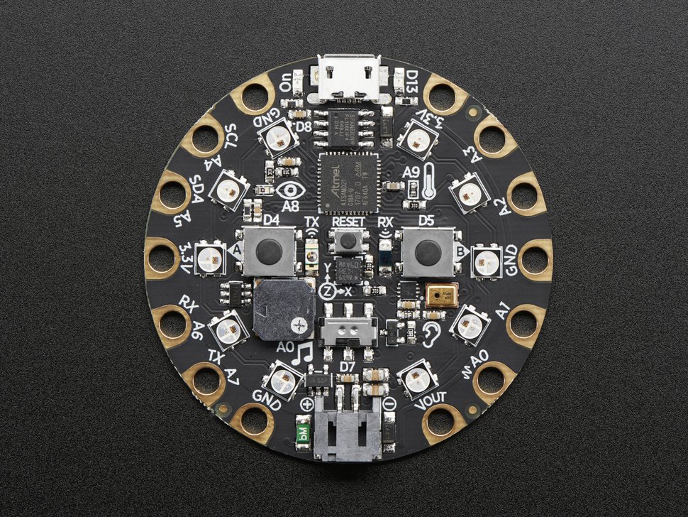
First up, this is effectively an Arduino (in essense), so I can use the Arduino software environment to program it (after downloading the right libararies), and set it up as I like. It's flat design and wide holes make it easy to sew into any piece of clothing. What's more, its jammed with extra features. Infra red control, accelerometer, in-built RGB LEDs, sound sensor, speaker, light sensor and more! All at a pretty cheap price (definitley cheaper than buying the components separately). It was perfect. The embedded LEDs could provide extra information that couldn't be shown on the 10x20 display, and the other features.... well, I didn't have an exact plan yet (well, maybe some TV remote control stuff), but what cool games console doesn't have a bunch of extra gimmicky features just waiting to be used?
But, as nice as that was, that's a far cry from controlling 200 LEDs. You see, the Playground Express only has about 8 pins/pads you can actually use (some are for power or ground).
The whole idea of an LED is you connect one end to power (5V), and one end to ground (0V), and it lights up. To control an LED, you usually set one end to ground always, and the other end to a control pin. Since you can control whether that pin is high (5V) or low (0V), you can then effectively control whether that LED is lit up or not. A simple software program can turn the LED on and off by controlling whether its associated control pin is high or low. In fact, this is usually the first thing one learns to do when working with the Arduino or other microcontrollers.
So, with 200 pixels to control, all we need is 200 control pins! At 8 pins per microcontroller:
200/8 = ... Okay, obviously we're not going to pepper the hoodie with 25 microcontrollers here. We need another option.
The Neopixels
One option was to not use the LED sequins, but instead use something else: Flora RGB Smart Neopixels
![]()
(I know I'm going on Adafruit stuff a lot here, but that's because wearable electronics are their specialty).
A Neopixel is, well, it's Adafruit's version of WS2811 or that sort of thing. Basically, its an LED that has a red, green and blue LED making it theoretically able to produce any colour depending on each light's brightness. It also has a control chip. The idea is that you daisy chain them together (they're often sold in strips), and the microcontroller only needs to connect to the first one in the chain. Once set up, you can control the brightness and colour of every single LED in the chain. Think of it like a train that gets sent down the line. Each time it hits a Neopixel, one of its carriges is taken off, that carrige is used to control that specifc LED, and the train continues on, with the same thing happening at each Neopixels it meets until it runs out of carriges or runs out of line.
Using the Neopixels would give me the ability to make my display have multiple colours. It would be easy to sew as I'd only need three conductive threads to go through each row in a zig zag pattern, not having to worry about overlaps... but it would come at a cost: Power.
At maximum, a Neopixel takes up 60mA. Cut that in half due to not being set to full brightness, and its 30mA. Multiply it by 200 and its 6000mA (6 Amps). Battery packs vary, but a good one would be on average around 5000mAh, meaning I'd get in the vague region of one hour of use out of a single battery before I'd either have to swap battery or start recharging it.
Honestly, it's doable? Especially for the convention circuit. But I wanted longer battery life (maybe too traumatised by memories of GameGear's short battery life as a child). I thought Neopixels were too overpowered and too expensive, and maybe I kinda just prefered to go for that red LED on black fabric aesthetic and felt that colour would just overwhelm it.
So I went back to the LED sequins.
Back in Time
When I talked about how each LED could be controlled by one control pin, I omitted mentioning that I'd dealt with this problem before.
A while back, I'd tried to make a digital pendulum clock which I did a write up about here. I had 6 digits with 8 LED segments per digit leading to a total of 48 LEDs I needed to control with only 22 control pins.
I solved it by doing multiplexing (more details at above link), essentially using transistors to only light up a single LED digit at a time. The idea is that by lighting up each of the 6 segments with their respective pattern in turn, you'd switch between them so fast it would blur to make it look like they were all lit up at the same time. Instead of needing 6x8 control pins (48), I only needed 6+8 control pins (14).
I could do something similiar with this!
Mutliplexing grids of LEDs is pretty simple. You basically have one group of wires for rows, and another group for columns The LEDs are laid out in a grid, and one side of the LED is connected to a column wire and the other side is connected to a row wire.

No two LEDs are connected to the same column AND row, this allows you to turn on each individual LED.
With this, you can light up each column with a specific pattern, and rapidly light up each remaining column in a different pattern so fast that they blur together so it looks like they're all lit up at the same time. You may have noticed this effect if you've ever taken a photo of an LED display, and noticed some columns (or rows) seem to be missing in the photo, even though the they were clearly there when you looked at the display with your own eyes.

Instead of needing 10x20 control pins (200), I'd only need 10+20 control pins (30).
Wait, 30 control pins?
That's still more than 8.... oh dear...
Advanced Multiplexing
The thing is, multiplexing is such a common thing that electronic need to do with LED displays, that you can find chips that do most of the work for you. With the Digital Pendulum Clock I wanted to do it all myself, and while it was a learning experience, it was also a huge mess of wires, transistor, resistors and connections. Doing that whole thing again, on a wearable, with 4 times as many LEDs... would get very, very messy.
So once again I go to Adafruit and find a HT16K33.
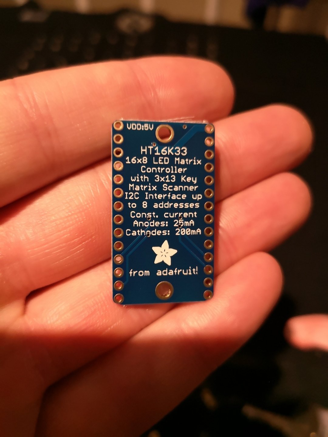
Chips like these do all the multiplexing for you. The chip has one set of pins for the rows, and one set for the columns. Also, this specific chip is on a breadboard with conductive holes for each individual pin. Generally, these holes are for putting other pins through and soldering them on, but for us they can be used for sewing them to the hoodie with conductive thread. As for how you control it? You only need to connect two wires from the microcontroller to the chip. That's it. Two wires. That's the I2C communication protocol.
So this is great! We control this with only two control wires (6 spare) and use it to control our 10x20 grid? Ummm, yet another problem approaches. This specific chip only has 16 pins for one side of the LED dissplay, and 8 pins for the other. That's 16x8. Tthat only lights up a maximum of 128 pins. And I couldn't find a version with more poins.
But that's still more than half of the pins we need taken care of, and with only two control pins used up. Can't I just get a second one to control the remaining LEDs?
Well... yes... in fact, that's what I decide to do... It's just not quite that simple.
Planning the grid.
The first HT16K33 was easy enough. Control the 16x8 LEDs at the top-left of the grid. That left 2 columns to the right, and 4 rows at the bottom, that were left unaddressed.
I repeatedly wrote out on a piece of paper in pencil different configurations for how to get a second HT16K33 to control the remaining LEDs. It was like some logic puzzle that I wasn't sure even had an answer. Each LED needed to be crossed over with two wires, and no two wires could connect to the same LED more than once. I was trying to take a grid pattern and stretch it so it worked with something that was only partially grid-like.
Finally, though, I had it.

With a lot of weaving wires back and forth, it worked.
Going sew sew
I took the sewing pattern and started cutting out the pieces I'd need. This time around I'd simplify it slightly, removing the front pockets for one. This meant sellotaping some of the patterns into one shape rather that cutting a bunch of separate patterns and sewing them together.
I located the piece that made up the back of the hoodie and started sewing in the LED sequins with conductive thread. I used a light bit of gloopy glue to hold the sequins in place before I sewed them in, using a ruler and marking chalk to make sure I had the grid spacings and positions right.
Made sure to sew in the HT16K33 into it.
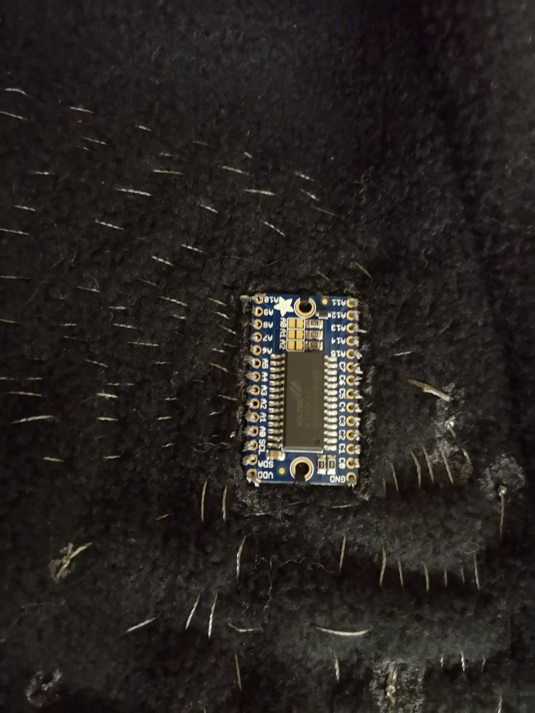
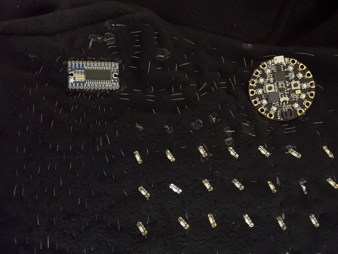
It took a lot of time. Trying to make sure they were tight, making sure that when two pieces of conductive thread overlapped, that one went over, and the other under. Trying to space them to avoid accidental connections.
After time I had the first grid wired up:
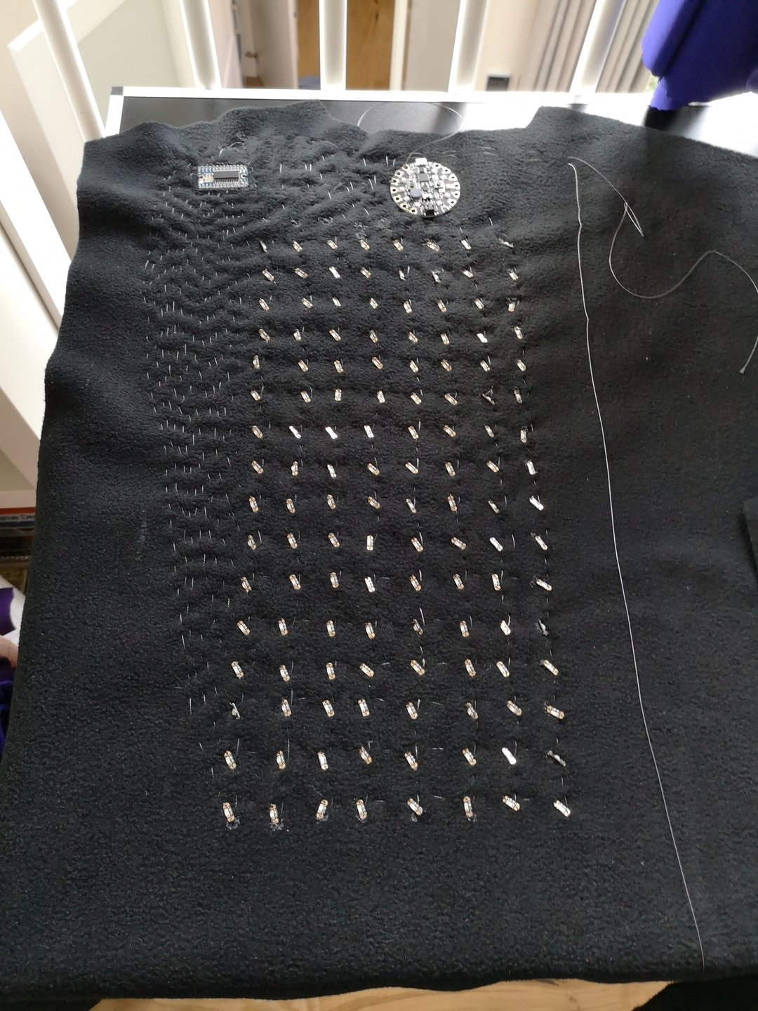
I could have left it here.. but no, I had to continue filling out the remaining 72 LED sequins!
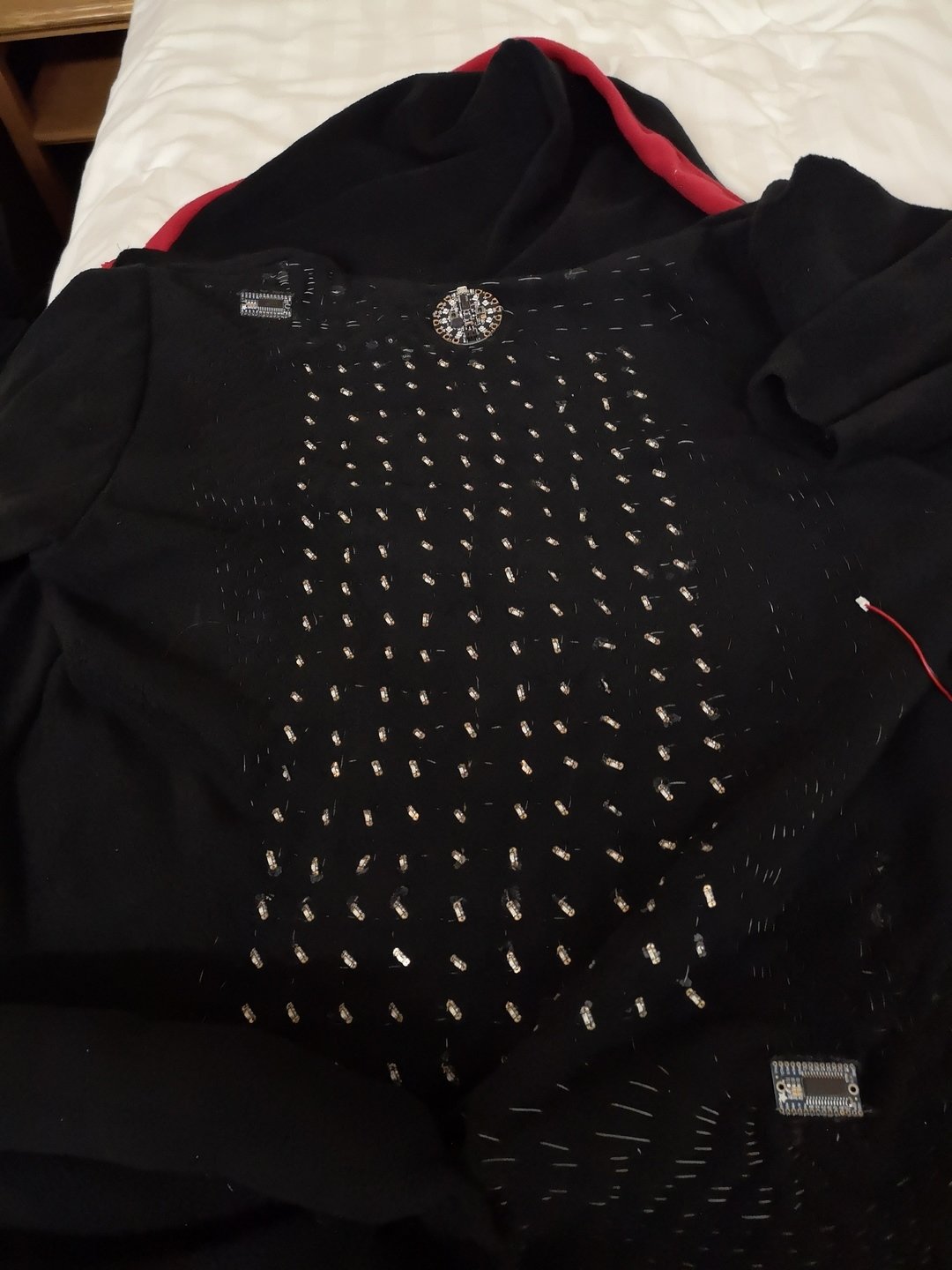
You might ask "If you were using two HT16K33's, and one of them required 2 wires to control, wouldn't you need 4 control wires total?" Well, no you don't! That's the genius of I2C! You can control multiple different chips and devices using only two control wires total. You just make sure all the SDA pins and all the SCL pins are wired together.
But how do you know which device you're using if they're all using the same wire? Well, you use a unique number for each device called an "address." Now all HT16K33 come with the same address by default, but they're easily customisable by whether or not you make 3 connections, giving you a total of 8 potential addresses for this specific chip. In my case, I was easily able to change the address of the second chip by putting a small blob of solder onto the appropriate place.
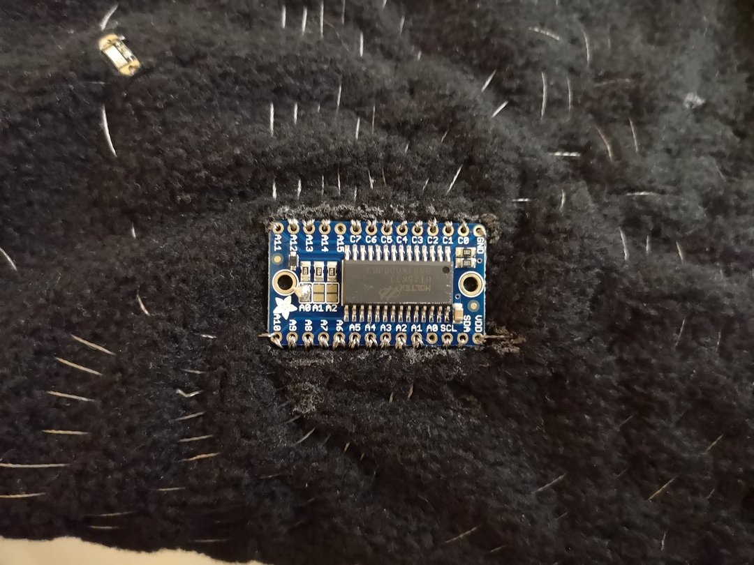
And so, with time and planning, all 200 LED sequins were finally wired up and controllable. Of course, due to my unorthodox wiring, it took a bit of coding to make sure any x,y coordinte ((0,0) being top left sequin) would be translated into the correct sequin lighting up. Basically there was a bunch of "if...else" statements. I'd like to say I was able to work out the code in advance, but honestly I used a bit of trial and error. Sending an x,y coordinate, and changing the code until the right LED lit up. I was able to figure out the patterns pretty quickly though, and soon I could light up any LED sequin with their proper coordinate without worrying how everything was wired up behind the scenes.
Power in your hands
With that done, I needed to work on the "gamepad", which of course would also be the tail. The tail would hang from the bottom of the back of my hoodie, and the very tip of it would be the gamepad. I wanted a nice soft plushie-like controller, and thankfully there are tutorials for this. Just as well its soft, cause it would probably be bouncing from leg to leg as I walked along with it.
It turns out, the Circuit Playground has libraries for "capacitive touch", a feature I decided to use. This meant two things:
- The buttons would be "touch sensitive", meaning the simple act of contact would trigger them. Good, because hard/switch buttons would be tricky to press on a soft surface.
- I would only need a single wire leading from each button to the Circuit Playground in order for them to work. Good, because I wanted to cut down on wires.
I decided to keep the control layout simple: One D-Pad and two buttons, 6 connections total. Since each button takes up a pin, and I had 6 pins to spare, this could all work... except that I would have to make sure 6 wires make it from the tip of the tail to the Playground at the top of the hoodie. To solve this, I decided to get a separate microcontroller to go between the buttons and the Playground. I chose the Flora which like the Playground is a sewable microcontroller with capacitive features that's made by Adafruit.
I cut out the polar fleece patterns somewhat like a MegaDrive controller, filled them with pillow stuffing, and made sure to sew in the flat conductive fabric with conductive thread.
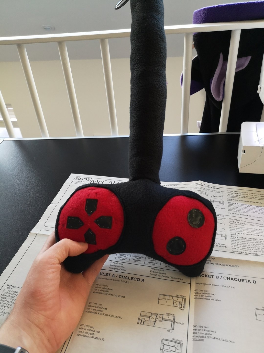
But how to get the connection between the buttons and the Flora? I used an ethernet cable of course. Each ethernet cable has 8 colour coded wires, so more than enough. I opened it at both ends, made the connection, and wrapped it in stuffing and the tail itself. Positioning the Flora at the base of the tail, I had it so it was wired via ethernet cable to all 6 buttons.
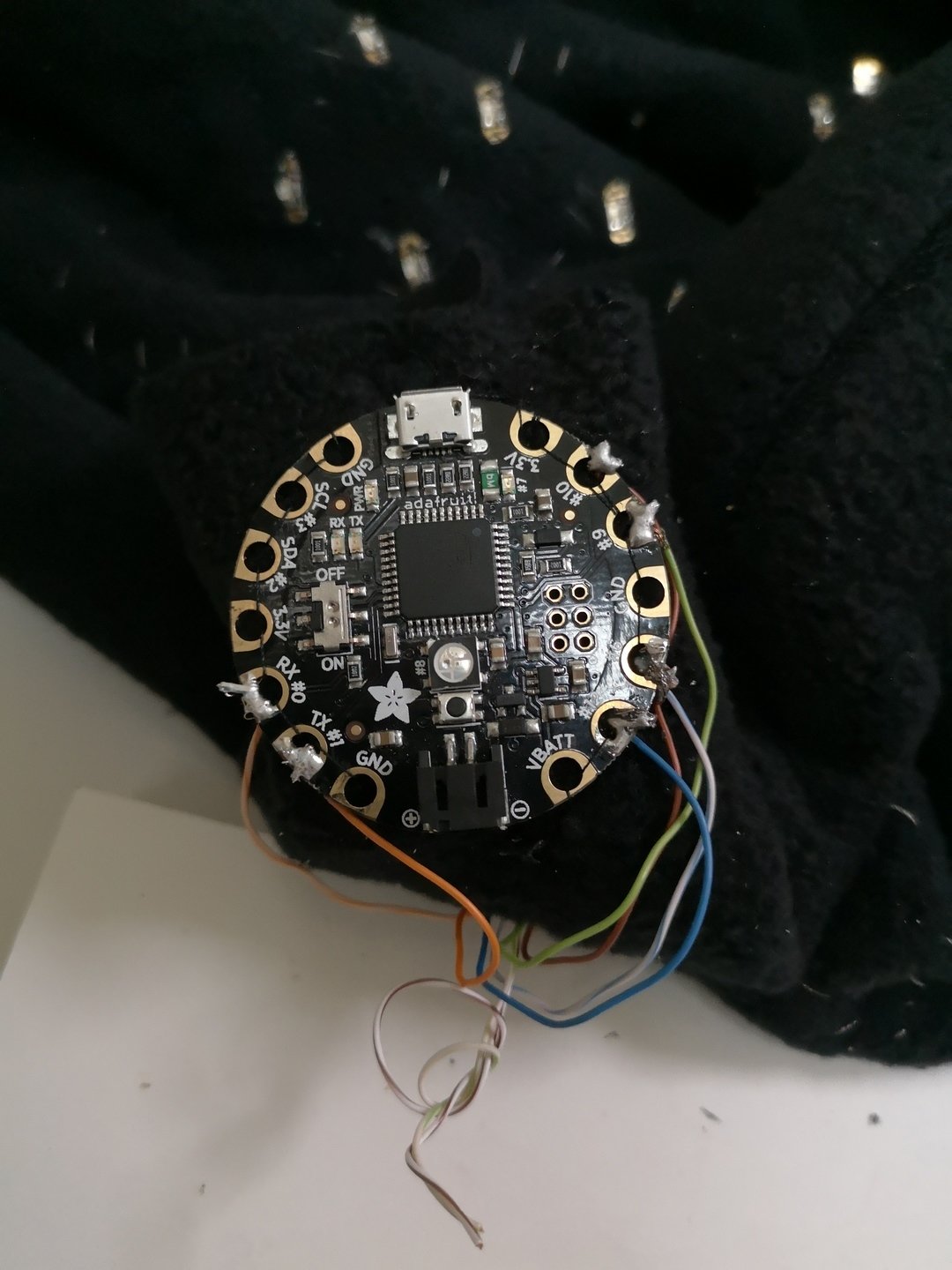
With the buttons wired up to the Flora, I programmed the basic touch detection, calibrated and did some testing. The buttons responded beautifully:
I then needed to connect the Circuit Playground that controlled the lights with the Flora that detected the buttons. I simply used I2C again. Now a Circuit Playground, a Flora and 2 HT16K33's were hooked up to eachother with the same two wires.

I learned something from this though. When you've got an I2C network, one single device must be set to master and the rest set to slaves. The HT16K33's are always slaves; but with the microcontrollers can be slaves or masters depending on how they are programmed. In my case, I decided the top Playground would be master and control all the major logic, and the bottom Flora would only be responsible for detecting and communicating buttons presses and so would be set to slave. Both were programmed as such.
True power
A few words on power:
Both the Flora and the Playground could be powered two ways, one is via USB port that you can connect to a computer or standard USB power pack. The other is a JST port which is designed for power. You can buy both LiON batteries with a JST cable that you can hook directly into the devices, or get a battery container for either AAA or AA batteries that has a JST cable coming out of it. All the above are available at Adafruit, and all seemed to power both pretty well.
I found I could power both the Flora and Playground at the same time with different power sources, but I needed to make sure that the Ground pins of the Playground and Flora were connected to eachother. If I didn't do this, they would sometimes kinda work and sometimes kinda not work in unpredictable ways (matrix, capacitor, etc), which in some ways is more annoying than if it didn't work outright. I would later learn that I could power both by a single power source if I also connected the Vout/Vbatt pins on both Circuit Playgrounds to eachother.
Be warned, there are travel restrictions on LiON batteries especially, so not only can they be tricky to order from the website (Adafruit has weird rules about how many you can buy in a single order), but also if you put a whole bunch of them in a plastic bag and take them in your carry on luggage on a flight, they may grab the interest of airport security (Though I got mine through fine after inspection, but just a warning).
The Launch
While unfortunately I wasn't able to have it ready for Confuzzled 2018, the convention I'd planned to make the hoodie for, I was able to bring it to the next convention right after it. Scotiacon!
It was all a bit last minute, I sewed the main parts together, even got a nice red hem around the hoodie part and the lower hem. Red zip. Even made ears that I pinned to the hood. Frantic last minute wiring, and it all seemed good.
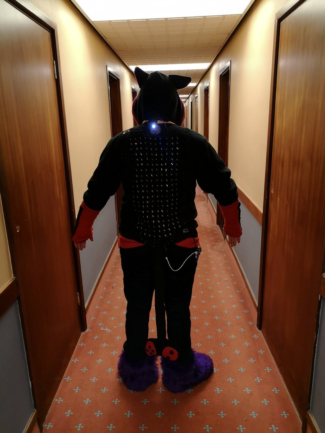
Except I had absolutely no games, whoops.
In fairness, every console has a shortage of games at launch, my console just had... no games at launch. (If by "launch" we mean "arriving at the convention with it")
I had the code ready for reading the gamepad input. I had the code for making sure I could put whatever pattern I wanted on the LED display matrix grid. It's just... all it could do right now was let you move a single red dot around the display using the gamepad. I mean, a nice demo, but not exactly a game.
My original plan had been to code Tetris, but right now, that was just way too complex to code. Maybe I could code a simpler game: Snake!
In the hotel room, on the bed with my laptop, I got to coding Snake. I was a bit nervous since it was taking up precious Convention time. Tapewolf (who I was rooming with) was remarkably patient as I hacked away at it and sent assurances to his way that I'd be done soon or just give up if it took too long. Thankfully, it turned out to be rather simple to code Snake, and I soon had something running. Time to head down to the convention floor and try it out with various congoers.
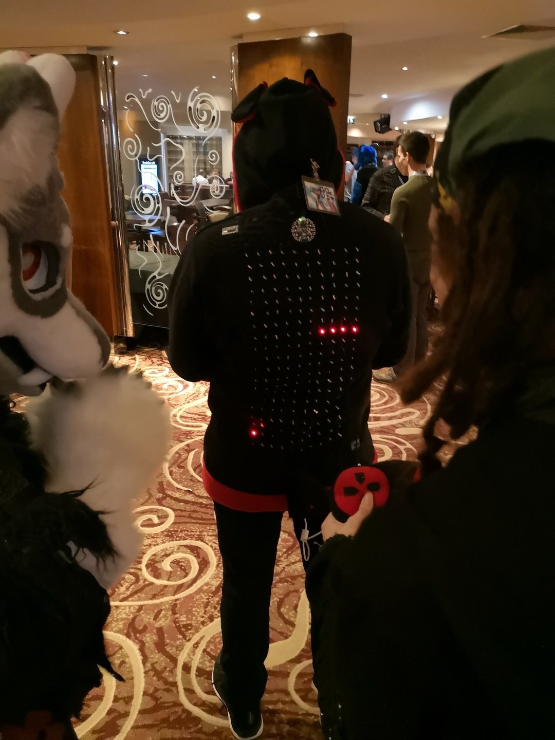
It worked!
While there was some "ghosting" where two rows would briefly repeat themselves (probably caused by folds in the fabric causing crossed wires). It was actually all pretty playable. It even gave the player the score at the end... if you were happy reading the score backwards.
Also got some nice attention on Twitter.
And of course, a video of it in action:
My mission to create a wearable console had been a success!
The Code
So what about the actual code to run the project?
Well, as I said, there were two Circuit Playgrounds, one handled the gamepad input, the other handled the LEDs, game code and everything else. The code's right here: