Digital Pendulum Clock
So ages ago I was watching an episode of Foster's Home for Imaginary Friends and I saw them walk past a clock shop with many different stylised clocks. Somehow this sparked an idea.
One thing I like doing is mixing the old and the new, the digital with the analogue, so I thought.... why not create a digital pendulum clock?
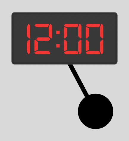
The idea would be there would be a great big red LED time display at top, and a pendulum swinging below it that would be keeping time.
It would be a cool piece to have. One key part I'd have is to make sure the pendulum is not decorative. If you held the pendulum, the time wouldn't advance. That was a fundamental part of the idea.
In order to work, clocks need something they can depend upon to count the time by. It has to be a dependable regularly occuring interval that they can then translate, into seconds, and then on to minutes and hours. Done well, they can pass an entire day without missing more than a second.
Pendulum clocks use pendulums that swing back and forth at regular intervals to keep time, traditional pocket watches used a spring that would oscilate back and forth, and modern digital clocks use quartz that can be made to oscillate at a precise frequency. Then there are atomic clocks which use the behaviour of atoms to keep time, making them the most accurate clocks in the world.
So my idea was pretty simple, make a regular digital clock, only use a pendulum for timekeeping rather than quartz or any other such system.
It was time to dive in.
First thing I needed was a digital display. Fortunately, it's pretty easy to get 7 segment LED display components. I bought them online from Maplins, which no longer exists, but you can get them at any regular electronics shop such as RS Online.
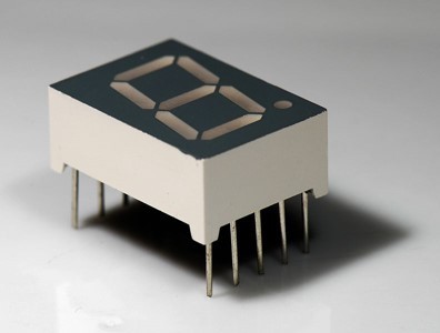
RS Online did a neat guide about these components here (and I've even stolen a few images from them) , but allow me to summarise.
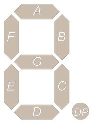
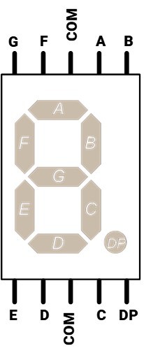
Each 7 segment display has 8 segments (yes, I know....), 7 for the number + 1 decimal point. Each segment is an LED strategically positioned so they can display different patterns depending on which ones are on.
The back of each segment has 9 pins (well, 10, but one is repated). One for ground (called COM), and one pin for each segment. You control which segments light up by applying a voltage to their respective pins, while ensuring the COM is always connected to ground (this setup is called common cathode, there's an alternative called common anode where the 8 pins go to ground and the remaining pin is set to a voltage, but we don't need to worry about that for this). Also, you'd usually put a resistor between COM and ground to slow the current so it doesn't burn out the LEDs.
So with a standard Arduino, you'd wire up the COM pin to ground (via a resistor), each of the 8 pins to one of the Arduino control pins, and simply write a program that controls which pins are set to high, so that you get whatever pattern you wanted.
As you can see, these LED displays are "dumb", you don't just tell it which number to display, you specifically control which segments are on and off and are in full control of what gets displayed.
However, there's a problem with this.
With 6 digits to display, and 8 pins needed per digit...
6 x 8 = 48
The Arduino Nano I would be using only had 22 control pins, so how could I control it?
Basically, instead of only controlling the LED's connection to power, and whether it receives power or not, you also control it's connection to ground. For an LED to work, it needs to be connected to both power and ground. Like a water wheel, you need water both entering and leaving in order to have a flow that you can get power from.
Controlling the power is easy, as I've explained, but controlling the access to ground requires something extra. A transistor.
A transistor is a switch, essentially. However instead of being a switch that you must physically move back and forth, you instead can control it by sending power to. Apply power to it, and the connection between two separate wires is open, release the power, and the connection closes (Some resistors will work the opposite way). In this case we apply voltage to the resistor via a really high resistor (about 1,000 Ohms).
So it becomes clear, set the positive side of the LEDs to control pins, and the negative side to ground via a transistor that's controlled by a set of other pins... but how does this reduce the amount of pins we're using? Shouldn't this actually double the amount of pins needed per LED?
Nope, because we're using what's known as multiplexing.
Instead of trying to light up the entire LED display at once, we basically only light up a single digit. Then light up the next, and the next, and the next and loop around to the first digit. We light them in sequence so fast, lighting each one in turn with their respective pattern, that to the human eye it all blends together.
So basically, 8 pins for the 8 LED segments, and 6 pins which determine which specific segments we're lighting up at that moment.
Instead of it being needing "6 x 8" pins, we only need "6 + 8" pins, in other words, 14 pins, which is definitely doable with the Arduino Nano.
Every segment will have 8 connections to the same 8 pins on the Arduino, and one connection to their own unique pin via a transistor that will control whether the segment as a whole is on or not.

So here's something. We've got 8 control pins, each of which needs to be connected to a control pin on each of the 6 segment displays. Then we've 6 more control pins that each need to be connected to a transistor, which goes between the COM of their respective segment, and Ground. Oh, and between the transistor and Ground is a resistor (about 220 Ohms), between the control pin and each transistor is another resistor (about 1,000 Ohms).
Won't this be incredibly messy to wire up?
Yes.
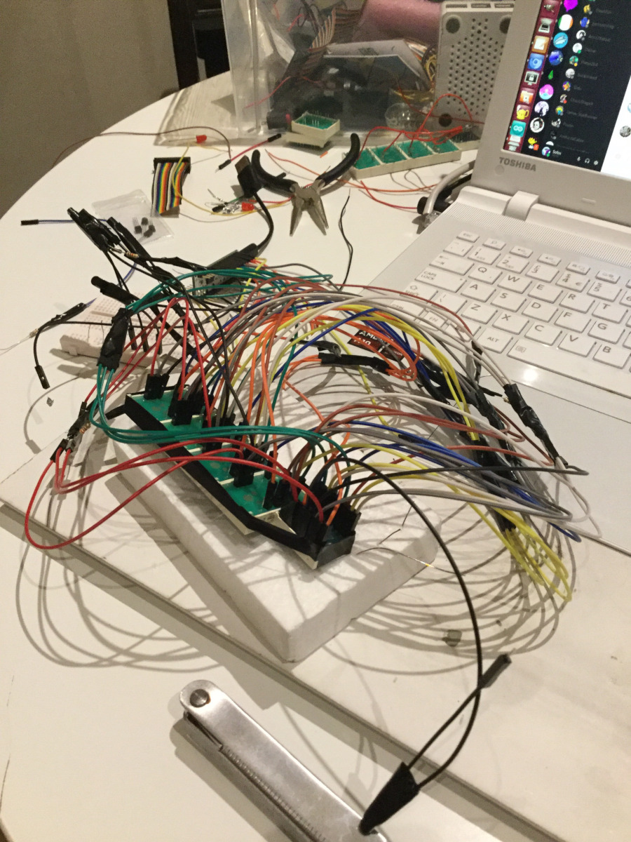
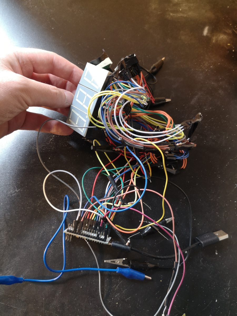
I probably should have been more sophisticated in how I joined the wires. Often I just wrapped them around eachother, then wrapped them up in tinfoil and electrical tape. Later on I bought these wire joiners which I just needed to insert the raw wires on and clamp it into place.
In short it was a mess, but I did it.
The display at least.
Now it was time for the pendulum.
So I got this
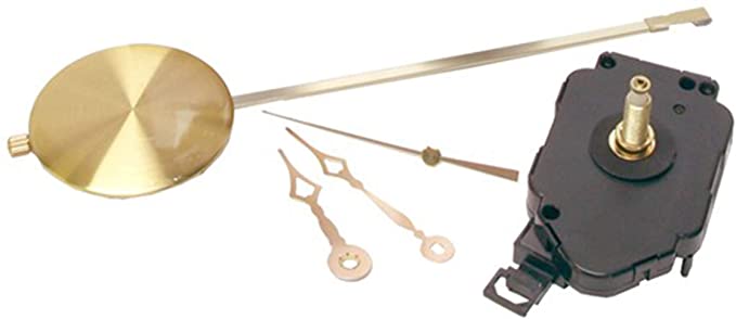
Seemed straightforward. Insert batteries, hang up, and get the pendulum swinging. It obviously came with hands but I didn't need them, just the pendulum system.
So how do we get the Arduino to detect when the pendulum swings?
With my old friend: Tinfoil!

Honestly, I'm surprised this doesn't get more use. Ever since I used wads of it as a kid to repair broken remote control battery contacts (and also creating my very first short circuit! Boy, did those batteries get hot) I have found it an invaluable standby when it comes to making electrical connections.
So I put one strip of tinfoil over the pendulum, attaching a wire to it, and another strip along the top of the pendulum with a different wire attached to it. When the pendulum hits the furthest end of its swing the two toinfoil pieces make contact. This effectively makes it a switch that the Arduino can detect (usually you set one end to high voltage, and the other end to a sensor pin as well as to ground via a high resistor (eg. 10,000 Ohms). Then the sensor pin detects high when the connection is made, and low when its broken).
So with all this set up, I need to code something to make it all work!
The code itself is right here: https://gist.github.com/TheSofox/6417ddc32f87ee5f9321190d65d9c207
But lets tackle the main bits.
int lnum [][10] = {{0,1,2,3,4,5,10},{1,2,10},{0,1,3,4,6,10}, {0,1,2,3,6,10},{1,2,5,6,10}, {0,2,3,5,6,10}, {0,2,3,4,5,6,10},{0,1,2}, {0,1,2,3,4,5,6,10},{0,1,2,3,5,6,10}};
Here's I made a list showing which segments to light up for each number. So the first number is zero, so it contains pretty much every segment except the middle dash, and the dot. The "10" is just at the end of the list to show that there's no more numbers to read.
void advanceTime(){
I decided to hand code the clock logic myself, storing the seconds, minutes and hours as separate variables. This function would add 1 to seconds. If it reached 60 seconds, the seconds would be set to 0 and 1 would be added to minutes. If minutes reached 60, minutes would be set to zero and 1 added to hours. If hours reached 24 then the hours would be set to 0. That's pretty much all you need for a digital clock.
int * getDigit(int digit, int place){
This function returns an array of segments to be lit up for a single digit, based on the list I wrote above. The "digit" is a number, ideally between 0 and 99. The "place" is 0 or 1, depending on which digit we wat from the 2 digit number we entered in as digit. This function gets called 6 times when we want to update the display, so that we can get the updated values for each of the 6 LED segments.
void writeLine(int s1[],int s2[], int s3[], int s4[], int s5[], int s6[]){
We've got our list of segments for each of our 6 numbers on display.
setSegment(0); setLed(s1); delay(del); setSegment(1); setLed(s2); ...
Set the transistor for the first digit to active, use the segment data to light up the led to the pattern we want, delay slightly, move to the next digit, use next segment data to light up the LEDs, delay, and so on.
Basically it rapidly goes through the 6 digits lighting them up to their respective patterns. This happens repeatedly, even when the numbers arn't changing.
int lowThreshold = 210; int highThreshold = 640; int ticking = false; int tickCount = 0; int lastVal; int countThreshold = 3; int highCount = 0; int lowCount =0;
I don't want to go into too much detail, but these are all the variables I had to tweak in order to properly detect when the two aluminium pieces touch eachother.
You see, ideally we want it that when they touch, we advance the clock. This means we detect when they're not touching, and then advance the clock when we detect that they do. However, there's a thing called bouncing where, upon making contact, they bounce off eachother a few times. So a single contact ends up getting registered as multiple contacts, and the clock could advance several seconds when it should only advance one (you may have heard of debounced switches which are switches set up to avoid such a thing). I set it up so that if there's more than one contact registered in a short period of time, only the first one is used to advance the time.
I basically kept tweaking these variables and the code underneath it, until it more or less worked.
And the result... is below!
Looks pretty cool huh? Getting the time to advance with the pendulum, being able to pause it, a genuine display!
However, gradually I realised a problem.
When I tried the pendulum clock against my wristwatch, I noticed that within a minute it seemed to go off by a few seconds. Sure, if it was losing a second or two in a day I wouldn't have too much of an issue, but within a minute.
I looked into things, and that's when I had a shocking realisation.
The pendulum kit I bought off Amazon... was decorative. The system that moved the pendulum back and forth was completely separate from the system that moved the clock forward. The clock wasn't using the pendulum to keep time. If you held onto the pendulum, the clock would keep ticking. It was most likely using a quartz crystal to keep time like every other digital clock. Meanwhile, some other mechanism kept the pendulum swinging for effect.
Because the pendulum wasn't tied to any sort of timekeeping, it didn't need to be accurate, just close enough to look good. This meant it wasn't near accurate enough for serious timekeeping for my system.
Frustrated, I went back online. Maybe another kit? But no, all the kits worked the same, just decorative. Most cheap pendulum clocks worked the same, just some magnet or something keeping the pendulum moving, while the clock ticked forward. Even that damn black and white cat clock that you used to see in movies was probably the same.
With a more discerning eye, I tried to look for actual pendulum clocks. One key difference is that these clocks tend to have a weight attached to them. This is what powers these clocks, a weight that gradually pulls downward. I was able to spot the real pendulum clocks, but the were either two expensive, or too classic to be worth hacking up for my project, or both! They were also rather complex, so adding the digital display would obviously make it a retrofit. Just might come across as tacky.
It seemed like I was spent. Months went by while the project kinda languished.
Then I had an idea. What about a 3D printed pendulum clock?
If I could make one, it would be relatively cheap, and I could hack away at it to my heart's content guilt free.
Looking up, I found a good model on Thingiverse, and went printing away.
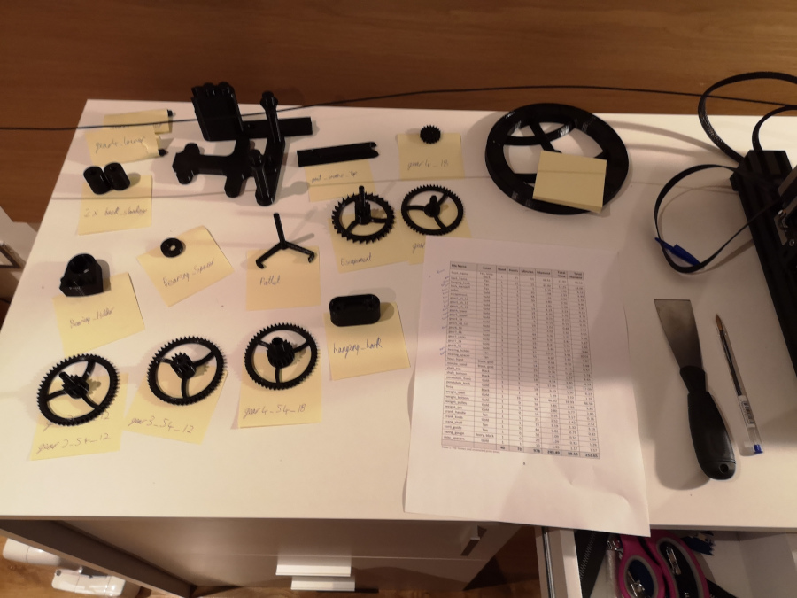
After printing the parts I tried to get the thing assembled. Unfortunately, I ran into two problems:
- The instructions were pretty complex and multiple pages long
- There was a big part list for stuff that couldn't be 3D printed. Each had a part number, but the part number only seemed to work in one American online shop that didn't ship to Ireland.
I tried to work through the instructions while trying to figure out which parts to substitute. I made trips to hardware shops, tried to make a list of which parts I needed and which online shops would work. Kept trying to make sure the parts I was getting were the same spefication as the parts on the list, and whether to get a simliar piece if the measurements didn't match. Also some of the copper rods needed to be filed? By how much...?
...eventually I just dropped it. I was nervous that even if I got the parts together it wouldn't work well. And there were so many literal moving parts to keep track of. It seemed like it would take a lot to get working
Since then a lot of other projects have taken my attention (some of which you can read about on this website. Even writing all this stuff for my website is a project in itself) and I've packed away the 3D printed pieces.
Maybe one day I'll return to this, but for now it's something I learned a lot from and moved on (check out my LED Hoodie for how I applied what I learned from this project).
So long Digital Pendulum Clock, maybe your time is still yet to come.